RATNA Co-Axial
Application
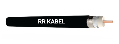
High quality co-axial for cable TV network for notch free attenuation values over wide range of frequencies. The special jacketing offers increased life even in rugged conditions.
Technical Data
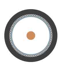
Conductor : The central conductor is made of soPd electrolytic grade annealed plain copper conductor, which has distinct advantages over traditional copper conductor.
Insulation : The insulation provided over the conductor is of foam PE
Screen : Aluminium mylar tape is provided over the insulated conductor to shield the conductor and ensures disturbance free transmission of signals
Braiding : The braiding is generally provided with 60% coverage of ATC (Annealed Tinned Copper) / Al alloy
Jacket : Specially formulated PVC, for rugged outdoor usage.
Marking : The cables are marked 'RATNA CO-X’
| Construction Details | Cable Type – Armoured |
| RG 59 F | RG 6 F* | RG 11 F |
| Part Number | 010501050791 | 010501060791 | 010501070791 |
| Inner conductor |
Copper |
Copper |
Copper |
| Nominal Diameter (mm) |
0.8 |
1.02 |
1.63 |
| Dielectric |
Foam PE |
Foam PE |
Foam PE |
| Nominal Diameter (mm) |
3.5 |
4.5 |
7.0 |
| Outer Conductor |
First |
Bonded Al Tape |
Bonded Al Tape |
Bonded Al Tape |
| Second |
Tinned Cu/Al Braid |
Tinned Cu/Al Braid |
Tinned Cu/Al Braid |
| Nominal Coverage (%) |
60 |
60 |
60 |
| PVC Jacket |
Black |
Black |
Black |
| Nominal Cable Diameter (mm) |
6.2 |
7.0 |
10.0 |
*RG 6 F is also available with CCS conductor and the applicable Part number shall be 010501040791.
| Construction Details | Cable Type – Armoured |
| RG 59 F | RG 6 F* | RG 11 F |
| Part Number | 010501050791 | 010501060791 | 010501070791 |
| Nominal Cable Diameter (mm) |
10.5 |
11.4 |
14.6 |
*RG 6 F armoured is also available with CCS conductor and the applicable Part number shall be 010501080791.s
Electrical Parameters
| Parameters | Cable Type |
| RG 11 F | RG 6 F* | RG 59 F |
| Inner Conductor-Max Resistance at 20°C (Ω/100m) |
0.8 |
2.1 |
3.43 |
| Nominal Capacitance (pF/m) |
53 |
53 |
53 |
| Characteristic Impedance (Ω) |
75 |
75 |
75 |
| Velocity of Propagation (%) |
85 |
85 |
85 |
| Dielectric Strength (KV) |
> 1 |
> 1 |
> 1 |
| Minimum Bending Radius (mm) |
75 |
65 |
60 |
| Maximum Attenuation at 20°C (dB/100m) at |
Max. |
Max. |
Max. |
| 5 MHz |
1.2 |
1.9 |
2.8 |
| 50 MHz |
3.1 |
5.3 |
6.7 |
| 100 MHz |
4.2 |
7.0 |
8.8 |
| 200 MHz |
6.0 |
9.9 |
12.4 |
| 250 MHz |
6.7 |
10.5 |
13.4 |
| 300 MHz |
7.3 |
11.5 |
14.6 |
| 350 MHz |
7.9 |
12.4 |
15.7 |
| 400 MHz |
8.5 |
13.3 |
16.7 |
| 450 MHz |
9.0 |
14.3 |
17.7 |
| 500 MHz |
9.5 |
14.9 |
18.7 |
| 550 MHz |
9.9 |
15.7 |
19.5 |
| 600 MHz |
10.4 |
16.4 |
20.3 |
| 750 MHz |
11.9 |
18.3 |
22.8 |
| 800 MHz |
12.4 |
19.5 |
24.5 |
| 900 MHz |
13.0 |
20.1 |
24.7 |
| 1000 MHz |
14.2 |
21.4 |
26.6 |


