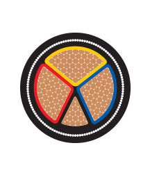
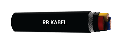
AYFY / YFY-AYWY / YWY-3.5 CORE
Cable Construction
1.1 kV (A.C) & 1.5 kV (D.C ) to Earth
3.5 cores AL /CU Conductor, PVC insulated, galvanised steel strip /wire armoured cables as per IS 1554 Part -1.
Conductor : AL/ CU Stranded compact shaped conductor as per Cl. 2, IS 8130
In CU 4 & 6 Sq. mm conductor are solid Cl. 1 or stranded class-2 as per IS 8130. 10 Sq. mm conductor is stranded Cl. 2 round as per IS 8130. Above 10 Sq. mm conductor are stranded compacted shaped Cl. 2 as per IS 8130
Above 10 Sq. mm conductor are stranded round or compact round or compacted shaped Cl. 2 as per IS 8130.
Insulation : PVC Type - A as per IS 5831. (Option : HR PVC Type - C, as per IS 5831)
Core Color : Red, yellow, blue
Inner Sheath : PVC / PVC tape as per IS 1554 (P - 1)
Armouring : Single armouring of galvanised steel strip / wire
Outer Sheath : PVC Type ST - 1 as per IS 5831 (Option : PVC Type ST - 2 as per IS 5831, FR Type, FRLS Type)
Cable Color : Black (Options : Any other color as per requirement)
Phase Core Color : Red, yellow, blue
Neutral Core Color : Black
Cable Design Parameters
While ordering, in addition to the part number the following details shall also be advised:
Conductor Type (Aluminium or Copper) and class of conductor (Cl. 1 or 2).
Insulation Type – PVC Type A / C.
Sheath Type – PVC Type ST – 1 / FR / FRLS; PVC Type ST – 2 / FR / FRLS.
| PartNumber | Nominal Cross Sectional Area (Sq. mm) | Minimum No. of Strands in Conductor | Nominal Thickness of Insulation (mm) | Minimum Thick. of Inner Sheath (mm) | Armouring with Flat AL Strip (AYFaY/YFaY) | Armouring with Round Wire (AYWaY/YWaY) |
| AL | CU | Nominal Thick. of Arm. Strip (mm) | Minimum Thick. of Out. Sheath(mm) | Approx. Overall Dia.(mm) | Approx Net Wtof Cable (kg/km) | Nominal Diameter of Wire (mm) | Minimum Thick. of Out. Sheath (mm) | Approx. Overall Dia. (mm) | Approx Net Wtof Cable (kg/km) |
| AL Cable AYFaY | CU Cable YFaY | AL Cable AYWaY | CU Cable YWaY |
| 110901010211 |
3×25+16 |
6/6 |
6/6 |
1.2/1.0 |
0.3 |
0.8 |
1.40 |
24 |
1000 |
1550 |
1.6 |
1.40 |
26 |
1285 |
1825 |
| 110901020211 |
3×35+16 |
6/6 |
6/6 |
1.2/1.0 |
0.3 |
0.8 |
1.40 |
26 |
1200 |
1950 |
1.6 |
1.40 |
28 |
1425 |
2125 |
| 110901030211 |
3×50+25 |
6/6 |
6/6 |
1.4/1.2 |
0.3 |
0.8 |
1.56 |
30 |
1500 |
2600 |
1.6 |
1.56 |
31 |
1785 |
2790 |
| 110901040211 |
3×70+35 |
12/6 |
12/6 |
1.4/1.2 |
0.4 |
0.8 |
1.56 |
34 |
1800 |
3300 |
2.0 |
1.56 |
36 |
2390 |
3780 |
| 110901050211 |
3×95+50 |
15/6 |
15/6 |
1.6/1.4 |
0.4 |
0.8 |
1.56 |
37 |
2300 |
4350 |
2.0 |
1.72 |
39 |
2980 |
4980 |
| 110901060211 |
3×120+70 |
15/12 |
18/12 |
1.6/1.4 |
0.5 |
0.8 |
1.72 |
41 |
2800 |
5450 |
2.0 |
1.88 |
43 |
3480 |
6080 |
| 110901070211 |
3×150+70 |
15/12 |
18/12 |
1.8/1.4 |
0.5 |
0.8 |
1.88 |
45 |
3200 |
6400 |
2.0 |
1.88 |
47 |
3970 |
7180 |
| 110901080211 |
3×185+95 |
30/15 |
30/15 |
2/1.6 |
0.5 |
0.8 |
2.04 |
49 |
3900 |
7900 |
2.5 |
2.04 |
53 |
5185 |
9150 |
| 110901090211 |
3×240+120 |
30/15 |
34/18 |
2.20/1.6 |
0.6 |
0.8 |
2.20 |
55 |
4800 |
10000 |
2.5 |
2.30 |
58 |
6385 |
11480 |
| 110901100211 |
3×300+150 |
30/15 |
34/18 |
2.4/1.8 |
0.6 |
0.8 |
2.36 |
61 |
5800 |
12300 |
3.2 |
2.52 |
65 |
8180 |
14480 |
| 110901110211 |
3×400+185 |
53/30 |
53/30 |
2.6/2.0 |
0.7 |
0.8 |
2.68 |
69 |
7300 |
15800 |
3.2 |
2.63 |
75 |
9885 |
18380 |
| 110901120211 |
3×500+240 |
53/30 |
53/34 |
3.0/2.2 |
0.7 |
0.8 |
2.84 |
77 |
9000 |
19500 |
4.0 |
3.00 |
84 |
13480 |
23985 |
| 110901130211 |
3×630+300 |
53/30 |
53/34 |
3.4/2.40 |
0.7 |
0.8 |
3.00 |
87 |
11500 |
25000 |
4.0 |
3.00 |
92 |
15980 |
28480 |
| Part Number | Nominal Cross Sectional Area(Sq. mm) | Max. DC Conductor Resistance at20°C (Ω/km) | Max. AC Conductor Resistance at70°C (Ω/km) | Approx.Capacitance of Cable (microF/KM) | Approx. Capacitance of Cable (microF/KM | Normal Current Rating (Amps) | Short CircuitCurrent Ratingfor 1sec. Duration(K.Amps) |
| With AL Cond. | With CU Cond. |
| AL | CU | AL | CU | Ground | Duct | Air | Ground | Duct | Air | AL | CU |
| 110901010211 |
3×25+16 |
1.2 |
0.727 |
1.44 |
0.87 |
0.083 |
0.42 |
76 |
63 |
70 |
99 |
81 |
90 |
1.9 |
2.88 |
| 110901020211 |
3×35+16 |
0.868 |
0.524 |
1.04 |
0.63 |
0.082 |
0.48 |
92 |
77 |
86 |
120 |
99 |
110 |
2.66 |
4.03 |
| 110901030211 |
3×50+25 |
0.641 |
0.387 |
0.769 |
0.464 |
0.082 |
0.49 |
110 |
95 |
105 |
145 |
125 |
135 |
3.8 |
5.75 |
| 110901040211 |
3×70+35 |
0.443 |
0.268 |
0.532 |
0.322 |
0.076 |
0.56 |
135 |
115 |
130 |
175 |
150 |
165 |
5.32 |
8.05 |
| 110901050211 |
3×95+50 |
0.32 |
0.193 |
0.384 |
0.232 |
0.076 |
0.58 |
165 |
140 |
155 |
210 |
175 |
200 |
7.22 |
10.9 |
| 110901060211 |
3×120+70 |
0.253 |
0.153 |
0.304 |
0.184 |
0.075 |
0.63 |
185 |
155 |
180 |
240 |
195 |
230 |
9.12 |
13.8 |
| 110901070211 |
3×150+70 |
0.206 |
0.124 |
0.247 |
0.1488 |
0.074 |
0.63 |
210 |
175 |
205 |
270 |
225 |
265 |
11.4 |
17.3 |
| 110901080211 |
3×185+95 |
0.164 |
0.0991 |
0.197 |
0.1189 |
0.074 |
0.64 |
235 |
200 |
240 |
300 |
255 |
305 |
14.1 |
21.3 |
| 110901090211 |
3×240+120 |
0.125 |
0.0754 |
0.151 |
0.0912 |
0.073 |
0.67 |
275 |
235 |
280 |
345 |
295 |
355 |
18.2 |
27.6 |
| 110901100211 |
3×300+150 |
0.1 |
0.0601 |
0.122 |
0.0733 |
0.073 |
0.68 |
305 |
260 |
315 |
385 |
335 |
400 |
22.8 |
34.5 |
| 110901110211 |
3×400+185 |
0.0778 |
0.047 |
0.0961 |
0.058 |
0.072 |
0.7 |
335 |
290 |
375 |
425 |
360 |
435 |
30.4 |
46 |
| 110901120211 |
3×500+240 |
0.0605 |
0.0366 |
0.0759 |
0.459 |
0.072 |
0.7 |
370 |
320 |
425 |
470 |
390 |
520 |
38 |
57.5 |
| 110901130211 |
3×630+300 |
0.0469 |
0.0283 |
0.061 |
0.0368 |
0.072 |
0.7 |
405 |
350 |
480 |
555 |
470 |
675 |
47.9 |
72.5 |


